• Skip to main content
  • Skip to footer

Dr Jody Muelaner

simplifying complexity

  • Home
  • Writing
  • Design
  • Contact

Case Study

Measurement Assisted Robotic Machining for Airbus

2013/06/26 by Jody Muelaner 2 Comments

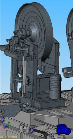
The Advanced Low Cost Aircraft Structures (ALCAS) project, led by Airbus, sought to reduce both the weight and cost of airliner wings. Jody Muelaner was the Technical Lead for Metrology on this project.

Interface Management

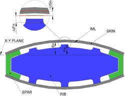
A key area of interest was the interface between the wing box ribs and the upper cover. The cover was produced using a resin infusion moulding technique. This produces the panel structure on a single sided mould with the outer aerodynamic profile tightly controlled, this is known as the outer mould line (OML). The inner profile which must interface with the spars and ribs is formed using a vacuum bag and is therefore not tightly controlled, this surface is known as the inner mould line (IML).

Jody supported the development by Airbus in the UK of a process to machine the wing box ribs during assembly to fit to the uncontrolled cover IML. This required accurate measurements of the cover IML to be made and for a flexible industrial robot to datum its-self and machine the rib feet with respect to these measurements.

Experiments were used to evaluate components of uncertainty

Uncertainty Modelling

The first phase of the work carried out was to model the uncertainty of the complete process in order to provide advice on process optimization and predicted capability. Jody was involved in developing innovative techniques for the modelling of metrology enabled processes, these were deployed in the modelling of this process. These techniques model the combined uncertainty of a complete process combining process variability with measurement uncertainty. Analytical uncertainty evaluation and Monte Carlo simulation are used to propagate these components of uncertainty to determine the combined process uncertainty.

Uncertainty evaluation was carried out

Filed Under: Automation, Case Study

Review of Large Volume Metrology for Airbus NGCW

2011/03/25 by Jody Muelaner Leave a Comment

Introduction

The Next Generation Composite Wing (NGCW) project is a £100M initiative led by Airbus to revolutionize aircraft wings in order to design, manufacture and test significantly lighter-weight and more eco-efficient aircraft. Jody Muelaner led a review of Large Volume Metrology Instruments covering instruments providing sub  millimeter measurement capabilities at scales of greater than 1 meter and typically in excess of 10 meters.

Graph of Instrument's Uncertainty against Range
Graph of Instrument’s Uncertainty against Range

Laser-Based Spherical Coordinate Measurement Systems

These systems combine laser ranging with two angle measurements to give coordinate measurements in 3 dimensions, such instruments include laser trackers and laser radar. The best state-of-the-art systems available (using multi-lateration) can achieve accuracy of 1 part in 106 of the measured range although 1 part in 105 is typical for coordinate measurements.

Principle of Operation for the Fringe Counting Interferometer in a Laser Tracker

Photogrammetry

Photogrammetry is essentially a theodolite network with cameras serving as automatic theodolites. Once a target has been located on a two dimensional image the direction of the target can then be determined from trigonometry. A major advantage of photogrammetry is that many points can be measured simultaneously. Accuracies of 1 part in 105 are typical.

Indoor GPS

Indoor GPS (iGPS) uses a number of transmitters around the working volume to fix the position of a single sensor. Communication from transmitter to sensor is one-way, so it is possible to have a large number of sensors simultaneously receiving signals and detecting their position. Accuracies of a few parts in 104 are typical.

Laser Projection

A point of laser light is rastered across an object to project templates and instructions for composite layup, painting, fitting bracketry etc. The laser projector is supplied with data describing the profiles to be projected, surfaces to project onto and reference features such as holes or corners. An integrated laser line scanner measures the reference features allowing the system to locate its-self within the virtual CAD environment before projection is carried out.

Filed Under: Case Study, Measurement

Machine Design for Stenner Saw Mills

2008/06/26 by Jody Muelaner Leave a Comment

Jody Muelaner has a wide range of experience in the design of industrial machinery. This has involved kinematic and structural design of mechanisms, chain and spur gears, pneumatics, hydraulics and electric drives.

A number of designs for feed systems were completed for Stenner; the biggest name in sawmill machinery. Some examples of these are illustrated here.

The work encompassed many aspects such as conceptual design, mechanism analysis, tolerance analysis, calculation of drive forces, specification of motors, buckling analysis etc.

Another Overhead Feed System
Conveyor Roundabout
Conveyor Roundabout
A Design for a Band Saw

Filed Under: Case Study, Design

Design of Plastic Lighting Enclosure for GDS

2006/08/17 by Jody Muelaner Leave a Comment

Jody Muelaner supported Global Design Solutions (GDS) in designing a new LED lighting product.
This design was considered aesthetics, ease of use and
ease of manufacture in injection moulded plastic.
FEA was used to optimise the clip design.

Concept Design

Jody was asked to design an enclosure that would provide for the ready
interchangeability of filters. Working closely with GDS at the concept
design stage assisted selection of a solution that met all of their requirements. A
bespoke circlip arrangement was chosen to secure the lens while blending into the overall aesthetics and allowing
lens removal without tools.

Detail Design and FEA Analysis

Analysis of the circlip was carried out to ensure that it would flex in the correct way to allow removal of
the lens by hand while also ensuring that peak stresses did not result in a reduced service life. Fundamental stress analysis was compared to FEA results to ensure accuracy and a full understanding of the behaviour of the component.
The design of components also had to consider the limitations of single part moulds since cost of tooling excluded more complex designs.

FEA Analysis of Circlip Deflection

Final Design Presentation

The finished design was presented as a series of fully rendered images. This
was requested to enable the marketing team at GDS to evaluate the design.

Photo Rendered Image of Design

Filed Under: Case Study, Design

Consumer Electric Heater Development for Electric Fires Technology

2006/06/23 by Jody Muelaner 1 Comment

Design Brief

This development work began with a concept for a more realistic flame effect. Previous electric fires had used a light mounted behind ribbons which were moved by an electric fan. As the ribbons move they obscure the light and create flame like images on a dark tinted glass screen. This new concept was to use a continuous sheet of slightly reflective silky material and to illuminate the front of this. This effect creates a far more realistic illusion of a fire.

Rendered Image of Flame Effect Fire

Optimization of Airflow

Early prototypes were able to give a very realistic impression of a fire but required fine tuning to achieve this. Initially Jody focused on optimising the airflow so that a consistent repeatable “flame picture” could be created in production conditions. This problem was complicated by the design requirement to use just one fan to drive both the flame picture and the flow through the heater element. As the heater element increases in temperature it causes the air to expand and creates a back-pressure. This reduces the flow velocity and further complicates the problem of maintaining a consistent flame picture.
For another example of a project involving the optimization of airflow see the Balanced Flue Case Study.

Safety Critical Factors

Design of the airflow was also of critical importance to safety considerations. For example in ensuring that the surface temperatures remained within acceptable limits and that the system shuts down safely in the event that vents were blocked while the heater element was activated. Various tests were conducted to ensure compliance with BS EN 60335.

Detail Design For Manufacture

In the final stages of the project Jody assisted in preparing the patent application and completed detailed design for manufacture of the sheet metal enclose. The client licensed the technology to a number of manufacturers for distribution throughout Europe. Jody completed a number of different detailed designs for a range of manufacturers.

Exploded View of Flame Effect Fire

Filed Under: Case Study, Design

FEA Failure Analysis of Pressure Vessel

2006/03/12 by Jody Muelaner Leave a Comment

Customer Profile and Brief

The Supplied 3D Model of the Cask

CypherCo are a manufacturer of specialist fluid transfer products for the beverage and agro-chemical industries world-wide. I was contracted to determine cause of failure on a moulded plastic cask under a 1 Bar internal pressure loading.

Problem Solution

Stresses acting on the barrel under an internal pressure loading were investigated using both finite element and classical analysis. I greatly simplified the supplied geometry to create a highly efficient axisymmetric finite element model allowing a very robust solution.

Axisymmetric Finite Element Model of Pressure Vessel

A convergence study was carried out on the maximum stress and total vertical deflection. This established the degree of mesh refinement required for accurate results and showed that stress results were accurate to within 5%. Coordinate systems were created on the weld lines so that normal and shear stress could be examined for each weld surface individually.

Cause of Failure

It was found that failure at the weld was most likely due to a combination of:-

  • A stress concentration in the surrounding geometry leading to peak
    stresses at the inner edge of the weld.
  • Further stress concentration at the weld edge due to the weld line
    its-self acting as a crack type stress raiser.
  • Possibly also an imperfect weld leading to less than full material
    strength in this region.
  • Classical analysis was used to determine the actual stress due to the
    weld line acting as a stress raiser.

Filed Under: Case Study, Design Tagged With: Case Study

FEA Contact Analysis of Biomedical Device for SRA Developments

2005/06/25 by Jody Muelaner Leave a Comment

Analysis Brief

SRA Developments are a leading innovator of ultrasonic medical devices. I carried out a detailed non-linear 3D surface contact Finite Element Analysis (FEA) for an assembly of titanium and glass fibre reinforced nylon parts.

An initial prototype for a new part had been produced by stereolithography, this part was not able to withstand the stresses incurred during normal use. Initial calculations suggested that a glass fibre reinforced nylon part might have the required strength. Considerable expense would be committed in tooling before the full strength part could be tested. I was contracted to carry out FEA analysis to determine if the part would have the required strength.

Initial Analysis

The first stage of analysis looked at the entire structure to determine the approximate levels of stress under normal use and the location of stress concentrations. A more detailed localized model was then created for the area of concern.

Linear Finite Element Analysis for Localized Model
Course Mesh Analysis of Whole Structure


Linear Analysis

An initial mesh was created for the localized model and a linear analysis was run. This mesh was then refined a number of times and the values for the maximum tensile and compressive stress were plotted against element count to show mesh convergence.

It was found that the value for the maximum tensile stress around the outer edge of the socket converged. This means that as the element count was refined the value tended towards a constant value. The value for the compressive stress did not converge. This is what might be expected. The linear loading creates a theoretically infinite stress along the lines of contact between the inner waveguide and the outer socket. As the mesh density is increased so the maximum stress increases.

Non-linear Contact Analysis

A non-linear analysis is necessary for two reasons:-

  • The contact does not take place along two lines of infinitesimal
    area. Instead the components deform creating a contact area. As the
    force is applied the contact area increases until the contact area
    multiplied by the contact stress is equal to the contact force.
  • The component will deform torsionally. This change the distribution
    of contact force. Since the open end of the socket deflects further than the end
    joined to the handle, the open end will transfer less of the force than
    the other end. This will have the effect of reducing the concentration
    of tensile stress on the outer circumference of the socket.

The first step in setting up this model for a non-linear analysis is to stabilise it using weak springs. This is important so that the full dynamic behaviour does not need to be modelled as the components initially move into contact.

Model Stabilized using Weak Springs

Next the boundary surface contact elements were created by setting up contact pairs. The outside surfaces were set to master to prevent surface normal errors.

The analysis was run many time in order to obtain convergence of the mesh density and a number of other non-linear parameters such as stability spring stiffness and penalty spring stiffness factor. The solution time was optimized by specifying activation distance for contact element generation to a value slightly greater than the maximum expected slide.

Mesh Detail
Mesh Detail

Results

The results indicated that a titanium insert would be required to obtain a reasonable service life. The suggested modification was made and the product was a success.

Filed Under: Case Study, Design

CFD Combustion Model for Yeoman Stoves

2003/06/25 by Jody Muelaner 1 Comment

I carried out computational fluid dynamics (CFD) modelling of the combustion process in a gas stove for Yeoman Stoves. This company constructs domestic gas stoves and originated the ‘balanced flue’ design which virtually eliminates the risk of carbon monoxide poisoning and increases efficiency. In a conventional design combustion actually causes cold air to be drawn into the building, in the least efficient designs this can actually result in a net cooling effect to the building as a whole!

The Balanced Flue Design:- The combustion chamber is sealed from the room. Cold air is drawn from outside via the outer ring in the flue.
The Balanced Flue Design:-
The combustion chamber is sealed from the room. Cold air is drawn from outside via the outer ring in the flue.

Despite the balanced flue design having a number of advantages general acceptance by the public had been limited due to the necessity to install an expensive and unsightly right angled flue on the outside of the building. My brief was to improve the efficiency of the design so that a simple strait flue could be used.

Mathematical Modeling

Combustion efficiency was improved by first considering the fundamental nature of the buoyancy driven flow, combustion and heat transfer. A complex mathematical relationship was established for the whole combustion process and an Excel model was created.

The process was simulated to determine certain unknown heat transfer coefficients. This involved creating a reliable mesh with over 140,000 elements volume elements; a mixture of Tet and Hex regions. Considerable effort was required to produce a mesh capable of reliably modeling the heat transfer coefficients of the surfaces containing the combusting gas while minimizing computational expense.

CFD Mesh containing a total of 140,000 elements

Coefficients were then incorporated into the mathematical model with variable parameters adjusted to optimize the combustion process. The optimized design was verified again using experimental results.

CFD Results Showing Surface Temperature Contours

Design for Manufacture

Considering the existing production process the required changes were developed into a design for manufacture. A prototype was constructed by Yeoman Stoves and this was then tested.

The Final Design Modeled in SolidWorks

The design allows a far simpler flue while improving combustion efficiency. Production costs for the complete product were reduced by 10%.

Filed Under: Case Study, Design

  • Page 1
  • Page 2
  • Go to Next Page »

Footer

Terms and Conditions
Privacy Policy
  • Facebook
  • Twitter
  • Linkedin
  • Research Gate
  • Google+

Copyright © 2025 · Infinity Pro on Genesis Framework · WordPress · Log in