• Skip to main content
  • Skip to footer

Dr Jody Muelaner

simplifying complexity

  • Home
  • Writing
  • Design
  • Contact

Jody Muelaner

Bicycle Suspension Analysis and Optimization presented in Seville

2015/04/13 by Jody Muelaner

Title: Kinematic Analysis and Optimization of Bicycle Suspension

Force exerted at the pedals of a bike cause an increase in vertical and horizontal ground reaction forces at the rear wheel, and also an increase in chain tension. Each of these forces results in a moment about the rear suspension pivot point. In the case of 4-bar linkage suspensions this remains true since the mechanism has an instantaneous centre. This bicycle suspension analysis shows that it is possible to optimize suspension geometry so that these moments remain in balance regardless of the gear selected.

Authors: J E Muelaner, T Knight, J Darling

Conference: Second International Conference on Sustainable Design and Manufacturing, Seville, Spain, 12-14 April

Download the full paper:pdf link icon

Download the spreadsheet to calculate the SAR for any bike:excel33x33

Abstract: Bicycle suspension is increasingly used to improve performance and facilitate the use of smaller wheels for folding bicycles, unwanted activation due to pedalling and braking forces can however result in energy losses. This paper presents a kinematic analysis leading to a Suspension Activation Ratio (SAR) which is the ratio of the suspension activation force to the pedalling force and its experimental verification. The SAR may be used as a performance metric to compare suspension designs and an objective function for suspension design optimization where the SAR is minimized for all possible gear ratios. Suspension geometry thus optimized shows agreement with optimal pivot positions found by empirical studies. Previous work has involved dynamic simulation and experimentation to estimate energy losses; however it is difficult to apply this analysis to rapidly evaluate different suspension designs for performance evaluation or design optimization. The kinematic design approach presented here provides the first step in suspension design which should precede dynamic design to optimize spring and damping rates. 2015 Conference Design

Filed Under: Design

Hybrid MSA and Uncertainty of Measurement presented in Seville, Spain

2015/04/12 by Jody Muelaner

Title: A hybrid Measurement Systems Analysis and Uncertainty of Measurement Approach for Industrial Measurement in the Light Controlled Factory

This is the first time that a practical industrial method has been presented which combines the tools of MSA and Uncertainty Evaluation. You can download the full paper here.

Authors: J E Muelaner, A J Francis, M Chappell, P G Maropoulos

Conference: Second International Conference on Sustainable Design and Manufacturing, Seville, Spain, 12-14 April

Download the full paper: pdf link icon

It may also be useful to download a supporting Gage R&R spreadsheet in Excel.

Abstract: The uncertainty of measurements must be quantified and considered in order to prove conformance with specifications and make other meaningful comparisons based on measurements. While there is a consistent methodology for the evaluation and expression of uncertainty within the metrology community industry frequently uses the alternative Measurement Systems Analysis methodology. This paper sets out to clarify the differences between uncertainty evaluation and MSA and presents a novel hybrid methodology for industrial measurement which enables a correct evaluation of measurement uncertainty while utilising the practical tools of MSA. In particular the use of Gage R&R ANOVA and Attribute Gage studies within a wider uncertainty evaluation framework is described. This enables in-line measurement data to be used to establish repeatability and reproducibility, without time consuming repeatability studies being carried out, while maintaining a complete consideration of all sources of uncertainty and therefore enabling conformance to be proven with a stated level of confidence. Such a rigorous approach to product verification will become increasingly important in the era of the Light Controlled Factory with metrology acting as the driving force to achieve the right first time and highly automated manufacture of high value large scale products such as aircraft, spacecraft and renewable power generation structures. 2015 Conference Measurement

Filed Under: Quality Assurance

What is lean manufacturing?

2015/04/03 by Jody Muelaner

Taking your understanding of lean manufacturing from a list of tools to a clear philosophy

Have you ever felt a bit confused about what exactly lean manufacturing really means? You probably find craft and mass production much easier to understand. They can be clearly defined. But at times lean can seem like a collection of different tools without a central philosophy.

If that’s the way you feel about lean manufacturing then trust me, you’re not alone. But lean really isn’t hard to understand, it’s just been explained badly. And I think there is a good reason for that.

As you will soon see, applying some lean tools is easy. But actually applying the philosophy of lean can be a bitter pill to swallow.

So the typical consultant or trainer will show you how to apply a few of the tools of lean manufacturing. Because he knows you will find this easy! But he won’t tell you what you don’t want to hear. Implementing the lean philosophy throughout an organisation is a huge and difficult transition.

But it is only by taking these big steps that you will transform  quality and productivity.

A brief history of manufacturing

I’m sure you already have a good idea about the different types of production that have been used in history. But it will help you understand the philosophy of lean manufacturing if you consider how it has developed.

filing metal partIn the beginning jobs were divided into ‘men’s work’ and ‘women’s work’. Next there was division into farmers, craftsmen, soldiers etc. In craft production one person may make a complete product from start to finish using highly adaptable tools. But often craftsmen are divided into more specialized roles. When craftsmen make machines the parts are filed to fit to together. If you need a new part it has to be filed to fit by another craftsman.

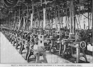
Long rows of milling machines in the Federal Armoury at Springfield in  190419th century American gun makers showed it was easier to make machines from interchangeable parts that fit together like Lego. In this ‘American system’ or ‘armoury practice’ a row of machines, each making a simple cut, would produce a standard part step-by-step. These machines didn’t need skilled craftsmen to operate them. Each machine was set against a gauge, and the gauges were set against a master part. This meant that all the parts would fit together without needing to be filed at the end. So assembly didn’t need skilled craftsmen either. Since the workers actually making things weren’t skilled they weren’t trusted to check the quality of their work. So inspectors and foremen were hired to maintain quality.

Henry Ford applied armoury practice to the point where each worker only carried out the simplest of operations. He was able to do this because he designed his car to be easy to make in this type of factory. Then he introduced the moving assembly line and mass production was born.

There is a steady progression away from skilled craftsmen using versatile hand tools and responsible for the quality of their own work. This is replaced by unskilled workers repeating simple operations on specialized machines with responsibility for quality given to inspectors.

 The Toyota Production System – Lean Manufacturing by another Name

In 1950 Eiji Toyoda wanted to save his family’s small car business – Toyota. He visited the vast Ford factory in Detroit for ideas. But he quickly realised that they could never compete by adopting mass production. The Japanese market needed small batches of several different vehicles. Their unions were strong and they didn’t have the immigrant work force that western manufacturers relied on for cheap labour. And there was another problem…

The Machine that Changed the World
The book that coined the term ‘Lean’ – essential reading


In mass production each of the 300 different steel panels for a car body is stamped on a different machine. They didn’t have money for hundreds of stamping machines. But Toyota’s chief engineer Taiichi Ohno found a solution. They must reduce the tool change time on the stamping machines. Then they could produce all the panels in small batches on just a few machines. Using rollers and simple adjusters they reduced the time from a day to just 3 minutes. After 10 years of development they could now efficiently produce a whole car body using just a few machines.

To their surprise parts produced in small batches actually cost less than mass produced parts! They didn’t have the cost of carrying inventory. But most importantly they could detect and correct stamping mistakes almost instantly.

At that point the essence of lean manufacturing was born. The trend away from versatile craftsmen was reversed. They kept the efficiency of machine made interchangeable parts. But they didn’t have unskilled workers doing repetitive jobs who didn’t notice quality. The production workers were making a wide range of different parts throughout the day. They were responsible for the tool changes, for checking quality and for getting to the root cause of an issues.

While the revolution in production methods was taking place there were also huge changes in labour relations. Redundancies and union action resulted in a new deal with the workers. They were guaranteed jobs for life with unheard of benefits but they were expected to do any job asked of them.

Ohno saw the inspectors, foremen, cleaners and repair men in mass production factories as ‘muda’ – waste. They weren’t adding value to the car. Instead workers were organized into teams with complete responsibility of their section of the assembly line. Instead of an idle foreman their team leader worked with the team. They did their own cleaning, repairs and quality-checking. The team even had time to discuss improving their process.

Allowing problems to move down the line before being inspected at the end was just more waste. If the problem wasn’t dealt with immediately then it would be repeated. So every worker had a cord above their work station. If they found a problem they couldn’t fix they could stop the line and the team would help them fix it. Then they would ask the ‘5 whys’ to get to the root cause. And they would find a way to stop it happening again ‘poka yoke’ (failure proofing).

The lean plant has two key organizational features, “It transfers the maximum number of tasks and responsibilities to those workers actually adding value to the car on the line, and it has in place a system for detecting defects that quickly traces every problem, once discovered, to its ultimate cause” (The Machine That Changed the World, Womack et al)

The transfer of responsibility down to those adding value was extended throughout the business. Subcontractors were organized into tiers so Toyota only dealt directly with ‘tier 1’ suppliers. The tier 1 suppliers were responsible for managing tier 2 suppliers and often also for the design of complete sub-systems. Similarly the sales force, who is after all dealing with the customers on a day to day basis, takes responsibility for gathering marketing data about the customers’ preferences.

Lean Manufacturing as a Gold Standard

The methods developed at Toyota were adopted by other Japanese companies but for a long time went unnoticed in the West. By the 1980’s there was a growing awareness that the west was falling behind the productivity of Japan. In 1984 the  International Motor Vehicle Program at MIT began a 5 year study. They would first study all of the tasks needed to make a car. Then they would visit producers around the world to see how they carry these out.

They found that the principles used by Toyota could work in every industry around the world with a huge benefit. They called these principles Lean.

So nobody invented ‘lean’! Toyoda, Ohno and others at Toyota created the ‘Toyota Production System’ and then years later a group of American professors studied it, called it ‘lean’ and told the world about it. The book they wrote is the clearest and most detailed explanation of the lean manufacturing system I’ve read. If you want to learn more then get this book.

The Machine that Changed the World
This is where the west first heard about Lean – if you haven’t ready this yet it is the place to start


Filed Under: Lean

Uncertainty of Runout Measurement – paper presented in Taiwan

2015/03/31 by Jody Muelaner

Title: Uncertainty of the Measurement of Radial Runout, Axial Runout and Coning using an Industrial Axi-Symmetric Measurement Machine

Authors: J E Muelaner, A J Francis, P G Maropoulos

Conference: 38th MATADOR Conference, Taiwan, 28 March

Download the full paper: pdf link icon

Abstract: This paper describes a method of uncertainty evaluation for axi-symmetric measurement machines which is compliant with GUM and PUMA methodologies. Specialized measuring machines for the inspection of axisymmetric components enable the measurement of properties such as roundness (radial runout), axial runout and coning. These machines typically consist of a rotary table and a number of contact measurement probes located on slideways. Sources of uncertainty include the probe calibration process, probe repeatability, probe alignment, geometric errors in the rotary table, the dimensional stability of the structure holding the probes and form errors in the reference hemisphere which is used to calibrate the system. The generic method is described and an evaluation of an industrial machine is described as a worked example. Type A uncertainties were obtained from a repeatability study of the probe calibration process, a repeatability study of the actual measurement process, a system stability test and an elastic deformation test. Type B uncertainties were obtained from calibration certificates and estimates. Expanded uncertainties, at 95% confidence, were then calculated for the measurement of; radial runout (1.2 µm with a plunger probe or 1.7 µm with a lever probe); axial runout (1.2 µm with a plunger probe or 1.5 µm with a lever probe); and coning/swash (0.44 arc seconds with a plunger probe or 0.60 arc seconds with a lever probe). 2015 Conference Measurement

Filed Under: Measurement

Rapid Machine Tool Verification developed for Rolls-Royce

2014/03/28 by Jody Muelaner Leave a Comment

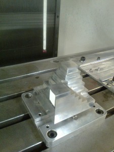
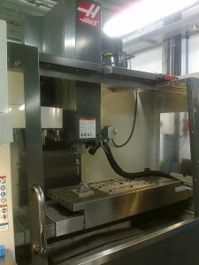
This work, carried out for Rolls-Royce, developed novel methods of verifying that machine tools are capable of machining parts to within specification, immediately before carrying out critical material removal operations, and with negligible impact on process times. The primary method used is artefact probing using touch trigger probes. This enables all the kinematic errors in a machine tool to be verified within 1-minute using a fully automated cycle with all data stored and processed natively on the machine tool controller. The verification cycle can therefore be called up as a sub-routine within machining programs and if the machine is no longer capable the process will stop and signal for machine maintenance.

Download:

Title: Rapid Machine Tool Verification

By J E Muelaner, B R Yang, C Davy, M R Verma, P G Maropoulos
Presented at the 8th International Conference on Digital Enterprise Technology – DET 2014 – “Disruptive Innovation in
Manufacturing Engineering towards the 4th Industrial Revolution in Stuttgart, Germany, 26-28 March 2014.

Abstract: This paper describes work carried out to develop methods of verifying that machine tools are capable of machining parts to within specification, immediately before carrying out critical material removal operations, and with negligible impact on process times. A review of machine tool calibration and verification technologies identified that current techniques were not suitable due to requirements for significant time and skilled human intervention. A ‘solution toolkit’ is presented consisting of a selection circular tests and artefact probing which are able to rapidly verify the kinematic errors and in some cases also dynamic errors for different types of machine tool, as well as supplementary
methods for tool and spindle error detection. A novel artefact probing process is introduced which simplifies data processing so that the process can be readily automated using only the native machine tool controller. Laboratory testing and industrial case studies are described which demonstrate the effectiveness of this approach.

Artefact Probing
Artefact Probing
Machine Tool running Rapid Verification Process

Filed Under: Machine Tool

Large Volume Metrology Technologies at DET 2014

2014/03/28 by Jody Muelaner Leave a Comment

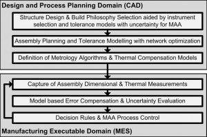
LCF Metrology Network Structure

This paper presents the vision for how the technologies of the Light Controlled Factory will enable Part-to-part assembly, Low cost flexible tooling and automation, Traceable quality assurance and control, reduced structural weight and greater aerodynamic performance. This will involve the following challenges; 1) controlling industrial robots for accurate machining; 2) compensation of measurements for thermal expansion; 3) Compensation of measurements for refractive index changes; 4) development of Embedded Metrology Tooling for in-tooling measurement and active tooling compensation; and 5) development of Software for the Planning and Control of Integrated Metrology Networks based on Quality Control with Uncertainty Evaluation and control systems for predictive processes.

Download:

Title: Large Volume Metrology Technologies for the Light Controlled Factory

By J E Muelaner, P G Maropoulos
Presented at the 8th International Conference on Digital Enterprise Technology – DET 2014 – “Disruptive Innovation in
Manufacturing Engineering towards the 4th Industrial Revolution in Stuttgart, Germany, 26-28 March 2014.

Abstract: In the Light Controlled Factory part-to-part assembly and reduced weight will be enabled through the use of predictive fitting processes; low cost high accuracy reconfigurable tooling will be made possible by active compensation; improved control will allow accurate robotic machining; and quality will be improved through the use of traceable uncertainty based quality control throughout the production system. A number of challenges must be overcome before this vision will be realized; 1) controlling industrial robots for accurate machining; 2) compensation of measurements for thermal expansion; 3) Compensation of measurements for refractive index changes; 4) development of Embedded Metrology Tooling for in-tooling measurement and active tooling compensation; and 5) development of Software for the Planning and Control of Integrated Metrology Networks based on Quality Control with Uncertainty Evaluation and control systems for predictive
processes. This paper describes how these challenges are being addressed, in particular the central challenge of developing large volume measurement process models within an integrated dimensional variation management (IDVM) system.

Filed Under: Measurement

A New Paradigm in Large Scale Assembly – Research Priorities in Measurement Assisted Assembly

2013/08/30 by Jody Muelaner Leave a Comment

This paper presents for the first time the concept of Measurement Assisted Assembly (MAA) and outlines the research priorities of the realisation of this concept in industry. MAA denotes a paradigm shift in assembly for high value and complex products and encompasses the development and use of novel metrology processes for the holistic integration and capability enhancement of key assembly and ancillary processes. A complete framework for MAA is detailed showing how this can facilitate a step change in assembly process capability and efficiency for large and complex products, such as airframes, where traditional assembly processes exhibit the requirement for rectification and rework, use inflexible tooling and are largely manual, resulting in cost and cycle time pressures. The concept of MAA encompasses a range of innovative measurement-assisted processes which enable rapid part-to-part assembly, increased use of flexible automation, traceable quality assurance and control, reduced structure weight and improved levels of precision across the dimensional scales. A full scale industrial trial of MAA technologies has been carried out on an experimental aircraft wing demonstrating the viability of the approach while studies within 140 smaller companies have highlighted the need for better adoption of existing process capability and quality control standards. The identified research priorities for MAA include the development of both frameless and tooling embedded automated metrology networks. Other research priorities relate to the development of integrated dimensional variation management, thermal compensation algorithms as well as measurement planning and inspection algorithms linking design to measurement and process planning.

Download:

Authors

P G Maropoulos1, J E Muelaner1, M D Summers2, O C Martin1

1: Department of Mechanical Engineering, University of Bath, Bath, UK

2: Airbus UK

Published in

The International Journal of Advanced Manufacturing Technology, 2013

Volume and page number information

DOI: 10.1007/s00170-013-5283-4

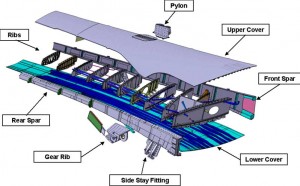
Exploded view of the ALCAS Wing Box
The ALCAS Wing Box which was used for the main Case Study

Filed Under: Part-to-part assembly

Thermal compensation

2013/08/23 by Jody Muelaner Leave a Comment

LIMA is now a partner on the European LUMINAR project. The aim of this project is to tackle several fundamental issues affecting users of Large Volume Metrology (LVM) equipment and techniques in industrial locations. By bringing advanced metrology to bear on these issues the consortium hopes to reinvigorate R&D efforts across Europe into LVM and to stimulate new opportunities and novel application areas, whilst retaining the traceability to the SI required for multi-national operations often encountered in the aerospace and science communities.

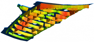
FEA Model of a Wing Cover Handling Frame
Thermal compensation of complex aerospace structures requires detailed modelling

LIMA is leading the work package to develop advanced modelling of multi-component assemblies is designed to enable end-users, particularly those in large aerospace or marine manufacture and assembly to demonstrate conformance to tolerance without expensive and energy-intensive thermal control of large environments such as aircraft hangars. Other work within the project will cover compensation of laser and photogrammetry based measurements for refractive index and turbulence effects. This should allow users in large factories and assembly locations to reduce the measurement uncertainties associated with existing and future optical-based measuring systems, thereby allowing more accurate alignment, machining and assembly. Compensation for the effects of refractive index variations can be an enabling step for future factory wide metrology networks, allowing progress towards the vision of the ‘future factory’. Demonstration of new traceable ADM technologies can allow the next generation of commercial instruments to achieve intrinsic traceability to the SI. The line-of-sight refractive index systems and ADM systems could be coupled to provide refractive index compensated reference lengths for other measuring systems, e.g. photogrammetry networks, helping instruments to maintain accuracy in uncontrolled environments.

Filed Under: Measurement

  • « Go to Previous Page
  • Page 1
  • Interim pages omitted …
  • Page 3
  • Page 4
  • Page 5
  • Page 6
  • Page 7
  • Interim pages omitted …
  • Page 10
  • Go to Next Page »

Footer

Terms and Conditions
Privacy Policy
  • Facebook
  • Twitter
  • Linkedin
  • Research Gate
  • Google+

Copyright © 2025 · Infinity Pro on Genesis Framework · WordPress · Log in