• Skip to main content
  • Skip to footer

Dr Jody Muelaner

simplifying complexity

  • Home
  • Writing
  • Design
  • Contact

Jody Muelaner

EasyChair for conference management

2013/08/11 by Jody Muelaner 8 Comments

I’ve used EasyChair in the past to submit papers to conferences but until recently I’d never used it to organize a conference. As part of helping to organize the Digital Enterprise Technology Conference in Stuttgart I needed to get to grips with EasyChair properly. I found it to be extremely unintuitive and the documentation/support to be appalling BUT it is a very useful and easy to use system once you know your way around. I therefore thought it would be useful to share my experiences here.

  • What EasyChair does
  • Issues with EasyChair
  • Conference Organisation Workflow (step-by-step)
  • Lessons Learned

What EasyChair does

EasyChair is a conference management system. This is an online database where authors can submit papers to a conference and panel members make themselves available to review papers. When a paper is submitted it can be tagged as relating to a specific topic. The program committee members specify which topics they have expertise in. The conference chair can then run an algorithm which automatically assigns papers to reviewers. Subsequently personalized batch email can be generated notifying all the panel members of which papers they have been allocated and then notifying authors of the reviewer decisions etc. There are many other options but this should give you then general idea; it should save a lot of work when organizing a conference!

Issues with EasyChair

First let me get the issues I have with EasyChair out of the way before explaining how useful it can be and where to find the options you need. Top of the list has got to be support. The help files and FAQ are very patchy and didn’t provide answers to any of the questions I had as I started to explore the interface. Many options are hard to find and when you do find them understanding what they do is a trial and error process. Hopefully this post will address some of these issues for users.

More seriously for a conference management system there is a lack of good data validation options. For example when an author submits a paper I want them to select tick boxes to indicate which topic their paper relates to. I would like validation rules to stop them from being able to submit if they have not selected a topic, or if they have selected more than one topic. I believe these data validation rules are missing, if they exist I haven’t found them yet! Similarly when an author is only submitting an abstract they may attach a pdf version of the abstract. The system then thinks it is a full paper, even if they have ticked the box saying “Abstract only”! These issues are troublesome but can be largely mitigated if you are aware of them by providing sufficient guidance in emails and other conference calls.

Conference Organisation Workflow

In this section I will explain how I performed a range of tasks in EasyChair following this workflow:-

  1. Setup the conference in EasyChair
  2. Invite Program Committee Members
  3. Send out Call for Abstracts
  4. Review Abstracts
  5. Accept Abstracts and request Full Papers
  6. Send out Call for Full Papers
  7. Assign Papers to Program Committee Members to Review
  8. email Decisions and Comments to Authors
  9. Send out Reminder that Final Paper is Required
  10. Check Final Papers
  11. Produce Conference Proceedings

Setup the conference in EasyChair

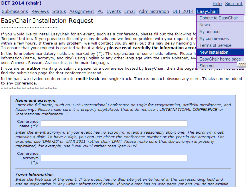
The process of creating a new conference in the EasyChair system is called creating a “new installation”. A request is made by logging into EasyChair and selecting EasyChair>New Installation from the main menu. You fill out a form and must then wait for this to be approved, they say normally within a few hours. I attempted to setup a test account to learn the system and I’m still waiting to hear if this will be allowed!

EasyChair New Installation Screen
New Installation Screen in EasyChair

Once the conference is ‘installed’ you will be able to manage it from within the EasyChair system. You will be able to select it from the main menu command EasyChair>My Conferences. Once selected you will be logged in as a conference chair. While you are logged in as a chair you have different menu options to those visible if you are logged in as an author. You can switch to author using the main menu command Conference Name>Change Role.

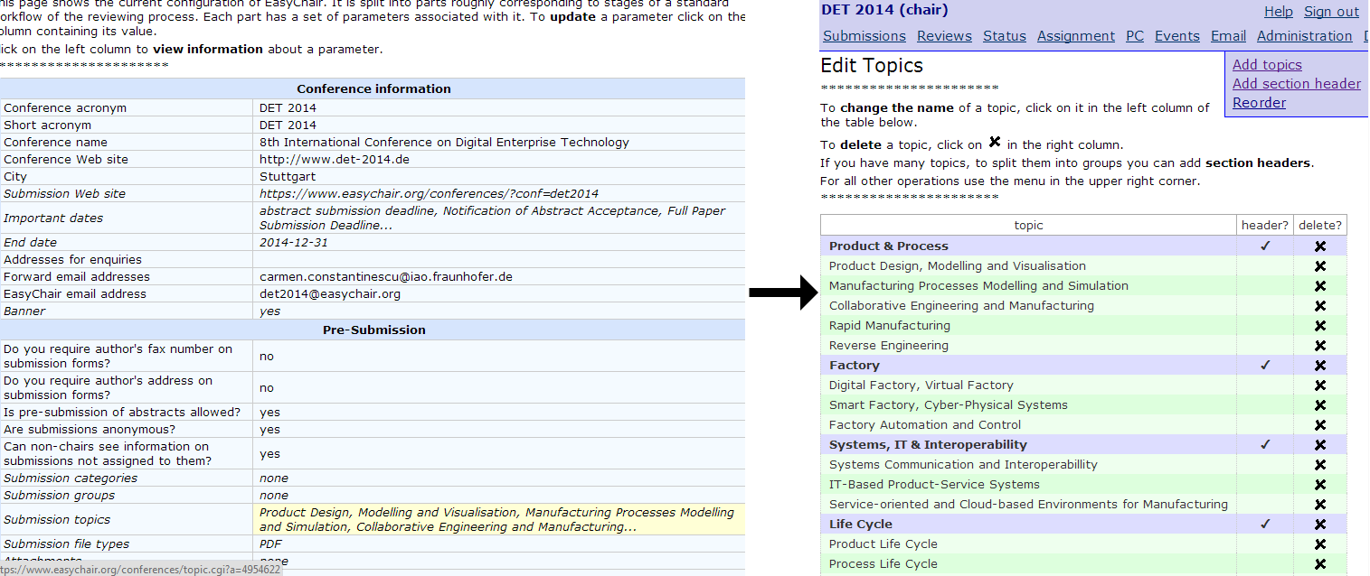
The conference is configured using the main menu command Administration>Configure. This takes you to a screen where you can enter details such as the name of the conference and select various options. I’m not clear what all the options do and will add a follow-up post explaining the configuration options when I have a better idea! It is important to define the conference topics at this stage. These will allow authors to indicate the topic of their paper during submission. It is then possible to automatically assign papers to relevant reviewers. In EasyChair there are topics, groups, categories and tracks. I haven’t worked out what exactly the differences are between these but topics worked for me.

You create the conference topics on the same  . The conference topics are located under the sub-heading ‘Pre-Submission‘ by clicking on ‘Submission topics‘. This then takes you to a screen where you can enter topics and section headings for the topics.

Screen Shots of Topic Definition in EasyChair
To Define Topics in EasyChair you first click on Topics in the Conference Configuration Screen

Invite Program Committee Members

You can invite Program Committee (PC) members using the main menu commands PC>Invitations to PC and then selecting Make invitation from the sub-menu. You enter the names and emails of the people you want to invite in a delimited format and a customized email is then sent to them with a link to accept. You should consider that the actual email they will receive will contain a standard invitation text and link before the custom email you compose. If they click the link to accept they will then receive another email with a link to the conference page on EasyChair, this will also inform them that if they do not currently have an account they will need to create one.

Send out Call for Abstracts

Although it is possible to send a call for abstracts from within EasyChair I decided to use a different system. I therefore can’t comment on the spending of a call from within EasyChair would work. I used the Newsletter plugin from with iur WordPress site.

It is important to consider how you will be processing the calls and include clear instructions in the call email. This is because the data validation and filtering is weak in EasyChar. For example it is possible to send customised emails to authors who have submitted abstracts only. But if an author attaches a pdf with their abstract then EasyChair thinks the have submitted a full paper. This is the case even if they have ticked the box saying “Abstract only”.

I included a warning that a topic must be selected or the reviewer would be automatically assigned. In future I would also include clear instructions that abstracts should be entered in the text box on the form only with no attachments unless a full paper was being submitted.

Review Abstracts

If all the abstracts have been entered correctly it becomes very easy to review them. You can view all abstracts as a single table by selecting the main menu command Reviews>All Papers. There is then a sub-menu command to toggle on and off the display of abstracts.

Screenshot of viewing all abstracts in EasyChair
Viewing all Abstracts in EasyChair (actual text from real submissions blurred)

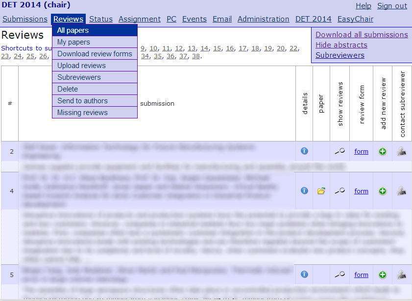
There is no easy way of selecting which are accepted/rejected while reading the abstracts. It is easy enough however to just make a note of this as you read through them.

Accept Abstracts and request Full Papers

Once you have reviewed the abstracts and decided which are accepted.. this article is a work in progress, please check back soon.

Send out Call for Full Papers

Once again I didn’t use EasyChair to send the call, I used the Newsletter plugin for wordpress.

I exported emails of those who had already submitted and used Excel to remove these emails.

.. this article is a work in progress, please check back soon.

Assign Papers to Program Committee Members to Review

.. this article is a work in progress, please check back soon.

email Decisions and Comments to Authors

.. this article is a work in progress, please check back soon.

Send out Reminder that Final Paper is Required

.. this article is a work in progress, please check back soon.

Check Final Papers

.. this article is a work in progress, please check back soon.

Produce Conference Proceedings

.. this article is a work in progress, please check back soon.

Lessons Learned

Abstract Submissions

For abstract submissions specifically request that authors do not attach any files. Certainly do not give them an abstract template to complete and attach. Instruct them to enter the text abstract using the online EasyChair form then it will then be very easy to review all the abstracts in a single table. EasyChair will also be able to tell you who has submitted an abstract and who has submitted a full paper. You will then be able to send customized mass email to these groups of authors.

Filed Under: management

Make a simple Groma!

2013/07/18 by Jody Muelaner 2 Comments

The Groma was the simple surveying tool used in Babylonia, Ancient Greece, Ancient Rome and Medieval Europe. It was constructed with a staff placed in the ground supporting a horizontal cross with 5 plumb lines handing from it. Understanding how a Groma works and can be self-compensated for accurate angle measurement is a great way to start gaining a full understanding of the principles of angle measurement and surveying. The Groma self-compensation and surveying experiments on this page, followed by a similar exercises relating to a theodolite, will serve as a great introduction to the principles of angle measurement and surveying.

The Groma allowed Accurate Surveying of Straight Lines and Right Angles

This simple experiment will substitute drawing pins pointing up for the plumb lines which were used as sighting lines and cardboard instead of a wooden frame. You will need the following:-

  • 9 Drawing Pins
  • A sheet of modelling card
  • Some sticky-back tape
  • Some blue tack
  • Scissors
  • A pen
The Materials You Will Need

First you will need to cut two small strips of card, each about 15 mm by 80 mm. I have used different colours to make them clearer to see but you could just cut them from the main sheet of card. You must then push a drawing pin through the end of each piece of card and one fixed in the main sheet of card, about 100 mm from one corner. If you are a child then ask an adult to help you do this.

Assembling the Pieces of Your Groma

Next push the strips of card into the fixed drawing pin in the main sheet of card to form a cross which can rotate about the central pin fixed in the sheet of card. Use a small piece of sticky-back tape to temporarily fix the angle between the two arms of the cross and also place another drawing pin poking up somewhere towards the other end of the large sheet of card. The drawing pins poking up from the arms of our ‘groma’ are equivalent to the plumb lines which are used for slighting along and the drawing pin poking up some distance away is a fixed point of reference which might be a tree or a building.

The Assembled ‘Groma’ and a Fixed Point of Reference

Now we can make our first sighting to align the ‘groma’ with our point of reference. Look down the length of the card past the ‘groma’ and towards the reference point and rotate the ‘groma’ until the sighting line pins at the ends both line up with the reference point.

First we Align the ‘Groma’ with the Fixed Reference Point

Next we would sight along the other pins arranged at a right angle to the first and an assistant would place a sighting rod in the ground. We will use drawing pins with blue-tack on the bottom in place of sighting rods!

Next we Place a ‘Sighting Rod’ in line with the other Arm of the ‘Groma’

Now we rotate the ‘groma’ through 90 degrees and repeat the procedure. The arm which was pointing at the ‘sighting rod’ is used to align the ‘groma’ with the fixed reference and the arm which was aligned with the fixed reference is used to place the ‘sighting rod’. If the ‘groma’ is not correctly adjusted this time the ‘sighting rod’ will be placed in a different position.

After Rotating the ‘Groma’ through 90 Degrees a Second ‘Sighting Rod’ is Placed

We place a third ‘sighting rod’ mid-way between the first two. The tape should be lifted to allow the arms of the cross to rotate relative to each other. It is now possible to correct the angle of the arms by aligning one with the fixed reference and the other with the mid-way ‘sighting rod’. The whole process can be repeated in order to increase the accuracy of your ‘groma’.

Final Adjustment of the ‘Groma’ is made by Placing a Third ‘Sighting Rod’ Mid-Way between the First Two and Rotating the Arms of the Cross to Point at both the Fixed Reference Point and the Mid-Way Sighting Rod

You have now performed a self-compensation of your ‘groma’ and are ready to place sighting rods along straight lines at right angles to each other to lay out the perfect Roman roads and city structures!

Filed Under: Measurement

Measurement Assisted Robotic Machining for Airbus

2013/06/26 by Jody Muelaner 2 Comments

The Advanced Low Cost Aircraft Structures (ALCAS) project, led by Airbus, sought to reduce both the weight and cost of airliner wings. Jody Muelaner was the Technical Lead for Metrology on this project.

Interface Management

A key area of interest was the interface between the wing box ribs and the upper cover. The cover was produced using a resin infusion moulding technique. This produces the panel structure on a single sided mould with the outer aerodynamic profile tightly controlled, this is known as the outer mould line (OML). The inner profile which must interface with the spars and ribs is formed using a vacuum bag and is therefore not tightly controlled, this surface is known as the inner mould line (IML).

Jody supported the development by Airbus in the UK of a process to machine the wing box ribs during assembly to fit to the uncontrolled cover IML. This required accurate measurements of the cover IML to be made and for a flexible industrial robot to datum its-self and machine the rib feet with respect to these measurements.

Experiments were used to evaluate components of uncertainty

Uncertainty Modelling

The first phase of the work carried out was to model the uncertainty of the complete process in order to provide advice on process optimization and predicted capability. Jody was involved in developing innovative techniques for the modelling of metrology enabled processes, these were deployed in the modelling of this process. These techniques model the combined uncertainty of a complete process combining process variability with measurement uncertainty. Analytical uncertainty evaluation and Monte Carlo simulation are used to propagate these components of uncertainty to determine the combined process uncertainty.

Uncertainty evaluation was carried out

Filed Under: Automation, Case Study

Latest Part-to-part Assembly Paper presented at CMS2013

2013/06/26 by Jody Muelaner Leave a Comment

This paper presents a complete framework for achieving part-to-part assembly though the use of measurement assisted assembly. It starts by setting out the objectives for low cost and high quality aero structure assembly. These objectives include achieving part-to-part assembly, low cost flexible automation and tooling, traceable quality assurance and control, reduced structure weight and improved aerodynamic tolerances.

It explains why challenges encountered in industries such as aircraft and spacecraft production mean that traditional approaches such as interchangeability are not cost effective at bringing about part-to-part assembly or improving structure tolerances. The alternative methods possible using measurement assisted assembly are shown to be more suitable in these industries. A complete digital architecture for the efficient implementation of measurement assisted assembly is shown in detail and the further development of measurement assisted assembly is presented as a roadmap to part-to-part assembly.

Part-to-part Assembly Paper Details

Download: Download the full part-to-part assembly paper: Achieving Low Cost and High Quality Aero Structure Assembly through Integrated Digital Metrology Systems

Title: Achieving Low Cost and High Quality Aero Structure Assembly through Integrated Digital Metrology Systems
By J E Muelaner, O C Martin, P G Maropoulos
Presented at the Forty Sixth CIRP Conference on Manufacturing Systems 2013 (CMS2013) in Portugal
Published in: Procedia CIRP, Volume 7, 2013, Pages 688–693

Abstract: Measurement assisted assembly (MAA) has the potential to facilitate a step change in assembly efficiency for large structures such as airframes through the reduction of rework, manually intensive processes and expensive monolithic assembly tooling. It is shown how MAA can enable rapid part-to-part assembly, increased use of flexible automation, traceable quality assurance and control, reduced structure weight and improved aerodynamic tolerances. These advances will require the development of automated networks of measurement instruments; model based thermal compensation, the automatic integration of ‘live’ measurement data into variation simulation and algorithms to generate cutting paths for predictive shimming and drilling processes. This paper sets out an architecture for digital systems which will enable this integrated approach to variation management.

Official URL: http://authors.elsevier.com/sd/article/S2212827113003235

Whole Part Predictive Fettling
Design for assembly decision process

Filed Under: Part-to-part assembly

Verification of the Indoor GPS System, by Comparison with Calibrated Coordinates and by Angular Reference

2012/07/17 by Jody Muelaner Leave a Comment

iGPS Transmitter
iGPS Transmitter

This paper details work carried out to verify the dimensional measurement performance of the Indoor GPS (iGPS) system; a network of Rotary-Laser Automatic Theodolites (R-LATs). Initially tests were carried out to determine the angular uncertainties on an individual R-LAT transmitter- receiver pair. A method is presented of determining the uncertainty of dimensional measurement for a three dimensional coordinate measurement machine. An experimental procedure was developed to compare three dimensional coordinate measurements with calibrated reference points. The reference standard used to calibrate these reference points was a fringe counting interferometer with the multilateration technique employed to establish three dimensional coordinates. This is an extension of the established technique of comparing measured lengths with calibrated lengths. The method was found to be practical and able to establish that the expanded uncertainty of the basic iGPS system was approximately 1 mm at a 95% confidence level. Further tests carried out on a highly optimized version of the iGPS system have shown that the coordinate uncertainty can be reduced to 0.25 mm at a 95% confidence level.

Download:

Authors

J E Muelaner1, Z Wang1, J Jamshidi1, P G Maropoulos1,
A R Mileham1, E B Hughes2, and A B Forbes2

1: Department of Mechanical Engineering, University of Bath, Bath, UK

2: National Physical Laboratory, Teddington, UK

Published in

The Journal of Intelligent Manufacturing, 2012

Volume and page number information

23(6), p. 2323-2331


Filed Under: Measurement

Metrology Enhanced Tooling for Aerospace (META): Strategies for Improved Accuracy of Jig Built Structures

2011/10/21 by Jody Muelaner Leave a Comment

Authors

J E Muelaner, O C Martin, P G Maropoulos

Department of Mechanical Engineering, The University of Bath, Bath, UK

Presented at

SAE Aerotech 2011

18-21st October 2011, Toulouse, France

Official URL

http://www.sae.org/events/atc/

Abstract

The accuracy of many aerospace structures is limited by the accuracy of assembly tooling which is in turn limited by the accuracy of the measurements used to set the tooling. Further loss of accuracy results from different rates of thermal expansion for the components and tooling. This paper describes improved tooling designs and setting processes which have the potential to significantly improve the accuracy of aerospace structures. The most advanced solution described is environmentally isolated interferometer networks embedded within tooling combined with active compensation of component pick-ups. This would eliminate environmental effects on measurements while also allowing compensation for thermal expansion. A more immediately realizable solution is the adjustment of component pick-ups using micrometer jacking screws allowing multilateration to be employed during the final stages of the setting process to generate the required offsets.

Download

References

  1. BOYES, W.E., JIGS AND FIXTURES. 1980, MICHIGAN: SOCIETY OF MANUFACTURING ENGINEERS.
  2. POLLOCK, H.W., TOOL DESIGN 2ND ED. 1988, NEW JERSEY: PRENTICE HALL.
  3. LEOPOLD, J., A. POPPITZ, M. KLARNER, A.K. SCHMIDT, AND J. BERGER, INTERACTION BETWEEN MACHINING AND NEW
    FIXTURING PRINCIPLES FOR AEROSPACE STRUCTURES. INTERNATIONAL JOURNAL OF MATERIAL FORMING, 2008.
    1(COMPENDEX): P. 531-533.
  4. MARTIN, O.C., J.E. MUELANER, AND P.G. MAROPOULOS. THE METROLOGY ENHANCED TOOLING FOR AEROSPACE (META)
    FRAMEWORK. 2010. MANCHESTER, UK.
  5. MUELANER, J.E. AND P.G. MAROPOULOS, DESIGN FOR MEASUREMENT ASSISTED DETERMINATE ASSEMBLY (MADA) OF LARGE
    COMPOSITE STRUCTURES. JOURNAL OF THE CMSC, 2010. 5(2): P. 18-25.
  6. ROOKS, B., ASSEMBLY IN AEROSPACE FEATURES AT IEE SEMINAR. ASSEMBLY AUTOMATION, 2005. 25(2): P. 108-111.
  7.  BURLEY, G., R. ODI, S. NAING, A. WILLIAMSON, AND J. CORBETT, JIGLESS AEROSPACE MANUFACTURE – THE ENABLING
    TECHNOLOGIES, IN SAE TECHNICAL PAPER SERIES. 1999, SAE INTERNATIONAL DOC
  8.  FLACK, D., MEASUREMENT GOOD PRACTICE GUIDE NO. 42: CMM VERIFICATION. 2001: NATIONAL PHYSICAL LABORATORY.
  9.  KAYANI, A. AND J. JAMSHIDI. MEASUREMENT ASSISTED ASSEMBLY FOR LARGE VOLUME AIRCRAFT WING STRUCTURES. IN 4TH
    INTERNATIONAL CONFERENCE ON DIGITAL ENTERPRISE TECHNOLOGY. 2007. BATH, UNITED KINGDOM. P. 426-434
  10.  LEICA, PCMM SYSTEM SPECIFICATIONS: LEICA ABSOLUTE TRACKER AND LEICA T-PRODUCTS. 2008.
  11.  AUTOMATED PRECISION INC, TRACKER3 LASER TRACKING SYSTEM. 2008.
  12.  FARO, LASER TRACKER ION TECH SHEET. 2010.
  13.  ASME, PERFORMANCE EVALUATION OF LASER-BASED SPHERICAL COORDINATE MEASUREMENT SYSTEMS, IN B89.4.19. 2006.
  14.  CIDDOR, P.E., REFRACTIVE INDEX OF AIR: NEW EQUATIONS FOR THE VISIBLE AND NEAR INFRARED. APPL. OPTICS, 1996. 35: P.
    1566-1573.
  15.  STONE, J.A. AND J.H. ZIMMERMAN. INDEX OF REFRACTION OF AIR. 2000 7TH DECEMBER 2004 [CITED 28 JULY 2008];
    CALCULATE WAVELENGTH IN AMBIENT CONDITIONS USING CIDDOR EQUATION]. AVAILABLE FROM:
    HTTP://EMTOOLBOX.NIST.GOV/WAVELENGTH/CIDDOR.ASP.
  16.  ESTLER, W.T., K.L. EDMUNDSON, G.N. PEGGS, AND D.H. PARKER, LARGE-SCALE METROLOGY – AN UPDATE. CIRP ANNALS –
    MANUFACTURING TECHNOLOGY, 2002. 51(2): P. 587-609.
  17.  MUELANER, J.E., Z. WANG, O. MARTIN, J. JAMSHIDI, AND P.G. MAROPOULOS, ESTIMATION OF UNCERTAINTY IN THREE
    DIMENSIONAL COORDINATE MEASUREMENT BY COMPARISON WITH CALIBRATED POINTS. MEASUREMENT SCIENCE AND
    TECHNOLOGY, 2010. 21 (2): P. 9 PAGES.
  18.  CALKINS, J.M., QUANTIFYING COORDINATE UNCERTAINTY FIELDS IN COUPLED SPATIAL MEASUREMENT SYSTEMS IN
    MECHANICAL ENGINEERING. 2002, VIRGINIA POLYTECHNIC INSTITUTE AND STATE UNIVERSITY: BLACKSBURG. P. 226.
  19.  SANDWITH, S. AUTOMATING LASER TRACKER CALIBRATION AND TECHNIQUE COMPARISON. IN LARGEVOLUME METROLOGY
    CONFERENCE. 2007
  20.  BSI, GEOMETRICAL PRODUCT SPECIFICATIONS (GPS) — STANDARD REFERENCE TEMPERATURE FOR GEOMETRICAL PRODUCT
    SPECIFICATION AND VERIFICATION, IN BS EN ISO 1. 2002.
  21.  FLACK, D. AND J. HANNAFORD, FUNDAMENTAL GOOD PRACTICE IN DIMENSIONAL METROLOGY – MEASUREMENT GOOD
    PRACTICE GUIDE NO. 80 MEASUREMENT GOOD PRACTICE GUIDE. 2005: NATIONAL PHYSICAL LABORATORY NPL.
  22.  HIBBELER, R.C., MECHANICS OF MATERIALS. 5TH ED. 2003, NEW JERSEY: PEARSON EDUCATION, INC.
  23.  ENGINEERING-ABC.COM. TRIBOLOGY: MECHANICAL PROPERTIES OF MATERIALS. 2010 [CITED; AVAILABLE FROM:
    HTTP://WWW.TRIBOLOGY-ABC.COM/ABC/PROPERTIES.HTM.
  24.  COE, P.A., D.F. HOWELL, AND R.B. NICKERSON, FREQUENCY SCANNING INTERFEROMETRY IN ATLAS: REMOTE, MULTIPLE,
    SIMULTANEOUS AND PRECISE DISTANCE MEASUREMENTS IN A HOSTILE ENVIRONMENT. MEASUREMENT SCIENCE AND
    TECHNOLOGY, 2004. 15(11): P. 2175-2187.
  25.  COE, P., D. HOWELL, R. NICKERSON, AND A. REICHOLD (2000) AN FSI ALIGNMENT SYSTEM FOR THE ATLAS INNER DETECTOR
    AND SOME EXTRAPOLATIONS TOWARDS NLC. VOLUME,
  26.  GIBSON, S.M., P.A. COE, A. MITRA, D.F. HOWELL, AND R.B. NICKERSON, COORDINATE MEASUREMENT IN 2-D AND 3-D
    GEOMETRIES USING FREQUENCY SCANNING INTERFEROMETRY. OPTICS AND LASERS IN ENGINEERING, 2005. 44(1): P. 79-95.
  27.  HUGHES, B., A. FORBES, W. SUN, P.G. MAROPOULOS, J.E. MUELANER, J. JAMSHIDI, AND Z. WANG, IGPS CAPABILITY STUDY, IN
    NPL REPORT NO. ENG 23. 2010, NPL: TEDDINGTON. P. 35, DOC
Split Bearing Located on Kinematic Mount and Three-Way Linear Slide

Filed Under: Part-to-part assembly

Integrated Dimensional Variation Management in the Digital Factory

2011/10/10 by Jody Muelaner Leave a Comment

Authors

J E Muelaner, P G Maropoulos
Department of Mechanical Engineering, The University of Bath, Bath, UK

Published in

Proceedings of DET2011 7th International Conference on Digital Enterprise Technology, Athens, Greece, 2011

Volume and page number information

39-46

Abstract

This paper describes how dimensional variation management could be integrated throughout design,
manufacture and verification, to improve quality while reducing cycle times and manufacturing cost
in the Digital Factory environment. Initially variation analysis is used to optimize tolerances during
product and tooling design and also results in the creation of a simplified representation of product
key characteristics. This simplified representation can then be used to carry out measurability
analysis and process simulation. The link established between the variation analysis model and
measurement processes can subsequently be used throughout the production process to
automatically update the variation analysis model in real time with measurement data. This ‘live’
simulation of variation during manufacture will allow early detection of quality issues and facilitate
autonomous measurement assisted processes such as predictive shimming.

A study is described showing how these principles can be demonstrated using commercially
available software combined with a number of prototype applications operating as discrete modules.
The commercially available modules include Catia/Delmia for product and process design, 3DCS
for variation analysis and Spatial Analyzer for measurement simulation. Prototype modules are used
to carry out measurability analysis and instrument selection. Realizing the full potential of
Metrology in the Digital Factory will require that these modules are integrated and software
architecture to facilitate this is described. Crucially this integration must facilitate the use of realtime
metrology data describing the emerging assembly to update the digital model.

Download


References

  1. Cai, B., Guo, Y., Jamshidi, J. and Maropoulos, P. G.,
    “Measurability Analysis Of Large Volume Metrology
    Process Model For Early Design”, 5th International
    Conference on Digital Enterprise Technology, Nantes,
    France, 2008
  2. Calkins, J. M. (2002). Quantifying Coordinate
    Uncertainty Fields in Coupled Spatial Measurement
    Systems Mechanical Engineering. Blacksburg,
    Virginia Polytechnic Institute and State University.
    PhD: 226.
  3. Dwyer, J. “Simulation – the digital factory.”
    Manufacturing Computer Solutions 5(3):1999 48-50
  4. Fabricius, F. “Seven step procedure for design for
    manufacture.” World Class Design to Manufacture
    1(2):1994 23-30
  5. Kayani, A. and Gray, I. (2009). Shim for Arrangement
    Against a Structural Component and a Method of
    Making a Shim, Airbus UK Ltd.
    46
  6. Kayani, A. and Jamshidi, J., “Measurement Assisted
    Assembly For Large Volume Aircraft Wing
    Structures”, 4th International Conference on Digital
    Enterprise Technology, Bath, United Kingdom, 2007
  7. Kuhn, W. “Digital factory – Simulation enhancing the
    product and production engineering process”,
    Monterey, CA, United states, 2006,
  8. Maropoulos, P. G., Bramall, D. G. and McKay, K. R.
    “Assessing the manufacturability of early product
    designs using aggregate process models.” Proceedings
    of the Institution of Mechanical Engineers, Part B:
    Journal of Engineering Manufacture 217(9):2003
    1203-1214
  9. Maropoulos, P. G., Yao, Z., Bradley, H. D. and Paramor,
    K. Y. G. “Integrated design and planning environment
    for welding Part 1: product modelling.” Journal of
    Materials Processing Technology 107(1-3):2000 3-8
  10. Muelaner, J. E., Cai, B. and Maropoulos, P. G., “Large
    Volume Metrology Instrument Selection And
    Measurability Analysis”, 6th International Conference
    on Digital Enterprise Technology, Hong Kong, 2009
  11. Muelaner, J. E., Cai, B. and Maropoulos, P. G. “Large
    Volume Metrology Instrument Selection and
    Measurability Analysis.” IMechE, Part B: J.
    Engineering Manufacture 224:2010 853-868
  12. Muelaner, J. E. and Maropoulos, P. G., “Design for
    Measurement Assisted Determinate Assembly
    (MADA) of Large Composite Structures”, CMSC,
    Reno, Nevada, 2010
  13. New River Kinematics (2007). SpatialAnalyzer.
  14. Stone, P. R. “Reconfigurable Fixturing”. Aerospace Manufacturing and
    Automated Fastening Conference and Exhibition, St. Louis, MS, USA, 2004
  15. Womack, J. P., Jones, D. T. and Roos, D. “The Machine
    that Changed the World”Rawson Associates New
    York1990
Integrated Digital Variation Management


Filed Under: Quality Assurance

Metrology enhanced tooling for aerospace (META): A live fixturing Wing Box assembly case study

2011/09/30 by Jody Muelaner Leave a Comment

Aerospace manufacturers typically use monolithic steel fixtures to control the form of assemblies; this tooling is very expensive to manufacture, has long lead times and has little ability to accommodate product variation and design changes. Traditionally, the tool setting and recertification process is manual and time consuming, monolithic structures are required in order to maintain the tooling tolerances for multiple years without recertification. As part of a growing requirement to speed up tool-setting procedures this report explores a coupon study of live fixturing; that is, automated: fixture setting, correction and measurement. The study aims to use a measurement instrument to control the position of an actuated tooling flag, the flag will automatically move until the Key Characteristic (KC) of the part/assembly is within tolerance of its nominal position. This paper updates developments with the Metrology Enhanced Tooling for Aerospace (META) Framework which interfaces multiple metrology technologies with the tooling, components, workers and automation. This will allow rapid or even real-time fixture re-certification with improved product verification leading to a reduced risk of product non-conformance and increased fixture utilization while facilitating flexible fixtures.

Authors

O C Martin1, J E Muelaner1, Z Wang1,
A Kayani2, D Tomlinson2, P G Maropoulos1, P Helgasson3

1 – Department of Mechanical Engineering, The University of Bath, Bath, UK
2 – Airbus UK
3 – Delfoi

Presented at

Proceedings of DET2011

7th International Conference on Digital Enterprise Technology

Athens, Greece
28-30 September 2011

Download

References

  1. Burley G, Odi R, Naing S, Williamson A and Corbett J,
    “Jigless aerospace manufacture – The enabling
    technologies”, in Aerospace Manufacturing
    Technology Conference & Exposition. Bellevue,
    Washington: Society of Automotive Engineers, 1999
  2. Durrantwhyte HF, “Sensor models and multisensor
    integration”, International Journal of Robotics
    Research, Vol. 7, No. 6, 1988, pp 97-113
  3. Gooch R, “Optical metrology in manufacturing
    automation”, Sensor Review, Vol. 18, No. 2, 1998, pp
    81-87
  4. Huang Y, Lan Y, Hoffmann WC and Lacey RE,
    “Multisensor Data Fusion for High Quality Data
    Analysis and Processing in Measurement and
    Instrumentation”, Journal of Bionic Engineering, Vol
    4, No. 1, 2007, pp 53-62
  5. Jayaweera N and Webb P, “Metrology-assisted robotic
    processing of aerospace applications”, International
    Journal of Computer Integrated Manufacturing, Vol.
    23, No. 3, 2010, pp 283-296
  6. Maropoulos PG, Guo Y, Jamshidi J and Cai B, “Large
    volume metrology process models: A framework for
    integrating measurement with assembly planning”,
    CIRP Annals – Manufacturing Technology, Vol. 57,
    No. 1, 2008, pp 477-480
  7. Martin OC, Muelaner JE, Tomlinson D, Kayani A and
    Maropoulos PG, “Metrology Enhanced Tooling for
    Aerospace (META) Framework”, Proceedings of the
    36th International MATADOR Conference,
    Manchester, 2010, pp 363-366
  8. Rooks B, “Assembly in aerospace features at IEE
    seminar”, Assembly Automation, Vol. 25, No. 2, 2005, pp 108-111
  9. Saadat M and Cretin C, “Dimensional variations during
    Airbus wing assembly” Assembly Automation, Vol.
    22, No. 3, 2002, pp 270-279
  10. Weckenmann A, Jiang X, Sommer KD, Neuschaefer-
    Rube U, Seewig J, Shaw L and Estler T, “Multisensor
    data fusion in dimensional metrology”, CIRP Annals –
    Manufacturing Technology, Vol. 58, No. 2, 2009, pp
    701-721
Hexapod
Hexapod


Filed Under: Quality Assurance

  • « Go to Previous Page
  • Page 1
  • Interim pages omitted …
  • Page 4
  • Page 5
  • Page 6
  • Page 7
  • Page 8
  • Interim pages omitted …
  • Page 10
  • Go to Next Page »

Footer

Terms and Conditions
Privacy Policy
  • Facebook
  • Twitter
  • Linkedin
  • Research Gate
  • Google+

Copyright © 2026 · Infinity Pro on Genesis Framework · WordPress · Log in