• Skip to main content
  • Skip to footer

Dr Jody Muelaner

simplifying complexity

  • Home
  • Writing
  • Design
  • Contact

Jody Muelaner

Study of the Uncertainty of Angle Measurement for a Rotary-Laser Automatic Theodolite (R-LAT)

2008/07/25 by Jody Muelaner Leave a Comment

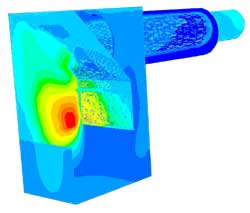
This paper shows how the angular uncertainties can be determined for a rotary-laser automatic theodolite of the type used in (indoor-GPS) iGPS networks. Initially, the fundamental physics of the rotating head device is used to propagate uncertainties using Monte Carlo simulation. This theoretical element of the study shows how the angular uncertainty is affected by internal parameters, the actual values of which are estimated. Experiments are then carried out to determine the actual uncertainty in the azimuth angle. Results are presented that show that uncertainty decreases with sampling duration. Other significant findings are that uncertainty is relatively constant throughout the working volume and that the uncertainty value is not dependent on the size of the reference angle.

Authors

J E Muelaner1, Z Wang1, J Jamshidi1, P G Maropoulos1,
A R Mileham1, E B Hughes2, and A B Forbes2

1: Department of Mechanical Engineering, University of Bath, Bath, UK

2: National Physical Laboratory, Teddington, UK

Published in

IMechE, Part B: J. Engineering Manufacture, 2008.

Volume and page number information

223(B3): p. 217-229

Notes

DOI

10.1243/09544054JEM1272

Download

References

  1. Hedges, T. M., Takagi, H., Pratt, T., and Sobel, M. J.
    Position measurement system and method using cone
    math calibration. United States Patent US 6,535,282 B2
    Mar. 18, 2003.
  2. Sharke, P. Measuring across space and time; large-scale
    metrology moves GPS in out of the rain. Mech. Engng,
    2003, 125(1), 48.
  3. Sell, C. On the right lines. Engineer, 2005, 293(7680), 30.
  4. Djurdjanovic, D. and Ni, J. Online stochastic control
    of dimensional quality in multistation manufacturing
    systems. Proc. IMechE, Part B: J. Engineering Manufacture,
    2007, 221, 865–880.
  5. Gottwald, R. SPACE – an automated non-contact
    3-D-measuring-system for industrial applications.
    Seventh International Conference on Robot Vision and
    Sensory Controls, Zurich, Switzerland, 2–4 Feb, 1988.
  6. Gilby, J. H. and Parker, G. A. Laser tracking system to
    measure robot arm performance. Sensor Rev., 1982, 2(3),
    180–184.
  7. Logsdon, T. The Navstar global positioning system, 1992
    (Chapman and Hall, London).
  8. Watson, J. T. A new approach to large coordinate
    measurement using four tracking interferometers. In
    Proceedings of the Third International Precision
    Engineering Seminar, Interlaken, Switzerland, 1985,
    pp. 68–71 (Butterworths, London).
  9. Hughes, E. B., Wilson, A., and Peggs, G. N. Design of a
    high-accuracy CMM based on multi-lateration techniques.
    Manuf. Technol., 2000, 49(1), 391–394.
  10. Zhang, D., Rolt, S., and Maropoulos, P. G. Modelling
    and optimisation of novel laser multilateration schemes
    for high-precision applications. J. Meas. Sci. Technol.,
    2005, 16, 2541–2547.
  11. Maropoulos, P. G., Zhang, D., Rolt, S., Chapman, P.,
    and Rogers, B. C. Integration of measurement planning
    with aggregate product modelling for spacecraft design
    and assembly. Proc. IMechE, Part B: J. Engineering
    Manufacture, 2006, 220, 1687–1695.
  12. Sprent, A. The Anglescan positioning system. The 25th
    Australian Survey Congress: Observing New Directions,
    Melbourne, Australia, 1983.
  13. Triggs, B., Mclauchlan, P., Hartley, R., and Fitzgibbon,
    A. Bundle adjustment – a modern synthesis. Lect. Notes
    Comput. Sci., 1999, 1883, 1–4.
  14. Brown, D. C. Densification of urban geodetic nets.
    Photogramm. Engng Remote Sens., 1977, 43(4), 447–467.
  15. Hadem, I. Bundle adjustment in industrial photogrammetry.
    Photogrammetria, 1981, 37(2), 45–60.
  16. ISO 10360-2:2002. Geometric product specifications
    acceptance and reverification tests for coordinate measuring
    machines (CMMs) – part 2: CMMs used for measuring
    size.
  17. ASME B89.4.19. Performance evaluation of laser-based
    spherical coordinate measurement systems, 2006.
  18. Industrial theodolites & total stations data sheet en.pdf.
    2008, available from http://www.leica-geosystems.com/
    corporate/en/products/total_stations/lgs_4387.htm.
  19. ISO 17123-1:2002. Optics and optical instruments – field
    procedures for testing geodetic and surveying instruments
    – part 1: theory.
  20. PD 6461-3:1995. General metrology. Guide to the
    expression of uncertainty in measurement (GUM).
  21. Bobroff, N. Recent advances in displacement measuring
    interferometry. Meas. Sci. Technol., 1993, 4(9),
    907–926.
iGPS Transmitter Centered on Rotary Table


Filed Under: Measurement

Machine Design for Stenner Saw Mills

2008/06/26 by Jody Muelaner Leave a Comment

Jody Muelaner has a wide range of experience in the design of industrial machinery. This has involved kinematic and structural design of mechanisms, chain and spur gears, pneumatics, hydraulics and electric drives.

A number of designs for feed systems were completed for Stenner; the biggest name in sawmill machinery. Some examples of these are illustrated here.

The work encompassed many aspects such as conceptual design, mechanism analysis, tolerance analysis, calculation of drive forces, specification of motors, buckling analysis etc.

Another Overhead Feed System
Conveyor Roundabout
Conveyor Roundabout
A Design for a Band Saw

Filed Under: Case Study, Design

Design of Plastic Lighting Enclosure for GDS

2006/08/17 by Jody Muelaner Leave a Comment

Jody Muelaner supported Global Design Solutions (GDS) in designing a new LED lighting product.
This design was considered aesthetics, ease of use and
ease of manufacture in injection moulded plastic.
FEA was used to optimise the clip design.

Concept Design

Jody was asked to design an enclosure that would provide for the ready
interchangeability of filters. Working closely with GDS at the concept
design stage assisted selection of a solution that met all of their requirements. A
bespoke circlip arrangement was chosen to secure the lens while blending into the overall aesthetics and allowing
lens removal without tools.

Detail Design and FEA Analysis

Analysis of the circlip was carried out to ensure that it would flex in the correct way to allow removal of
the lens by hand while also ensuring that peak stresses did not result in a reduced service life. Fundamental stress analysis was compared to FEA results to ensure accuracy and a full understanding of the behaviour of the component.
The design of components also had to consider the limitations of single part moulds since cost of tooling excluded more complex designs.

FEA Analysis of Circlip Deflection

Final Design Presentation

The finished design was presented as a series of fully rendered images. This
was requested to enable the marketing team at GDS to evaluate the design.

Photo Rendered Image of Design

Filed Under: Case Study, Design

Consumer Electric Heater Development for Electric Fires Technology

2006/06/23 by Jody Muelaner 1 Comment

Design Brief

This development work began with a concept for a more realistic flame effect. Previous electric fires had used a light mounted behind ribbons which were moved by an electric fan. As the ribbons move they obscure the light and create flame like images on a dark tinted glass screen. This new concept was to use a continuous sheet of slightly reflective silky material and to illuminate the front of this. This effect creates a far more realistic illusion of a fire.

Rendered Image of Flame Effect Fire

Optimization of Airflow

Early prototypes were able to give a very realistic impression of a fire but required fine tuning to achieve this. Initially Jody focused on optimising the airflow so that a consistent repeatable “flame picture” could be created in production conditions. This problem was complicated by the design requirement to use just one fan to drive both the flame picture and the flow through the heater element. As the heater element increases in temperature it causes the air to expand and creates a back-pressure. This reduces the flow velocity and further complicates the problem of maintaining a consistent flame picture.
For another example of a project involving the optimization of airflow see the Balanced Flue Case Study.

Safety Critical Factors

Design of the airflow was also of critical importance to safety considerations. For example in ensuring that the surface temperatures remained within acceptable limits and that the system shuts down safely in the event that vents were blocked while the heater element was activated. Various tests were conducted to ensure compliance with BS EN 60335.

Detail Design For Manufacture

In the final stages of the project Jody assisted in preparing the patent application and completed detailed design for manufacture of the sheet metal enclose. The client licensed the technology to a number of manufacturers for distribution throughout Europe. Jody completed a number of different detailed designs for a range of manufacturers.

Exploded View of Flame Effect Fire

Filed Under: Case Study, Design

FEA Failure Analysis of Pressure Vessel

2006/03/12 by Jody Muelaner Leave a Comment

Customer Profile and Brief

The Supplied 3D Model of the Cask

CypherCo are a manufacturer of specialist fluid transfer products for the beverage and agro-chemical industries world-wide. I was contracted to determine cause of failure on a moulded plastic cask under a 1 Bar internal pressure loading.

Problem Solution

Stresses acting on the barrel under an internal pressure loading were investigated using both finite element and classical analysis. I greatly simplified the supplied geometry to create a highly efficient axisymmetric finite element model allowing a very robust solution.

Axisymmetric Finite Element Model of Pressure Vessel

A convergence study was carried out on the maximum stress and total vertical deflection. This established the degree of mesh refinement required for accurate results and showed that stress results were accurate to within 5%. Coordinate systems were created on the weld lines so that normal and shear stress could be examined for each weld surface individually.

Cause of Failure

It was found that failure at the weld was most likely due to a combination of:-

  • A stress concentration in the surrounding geometry leading to peak
    stresses at the inner edge of the weld.
  • Further stress concentration at the weld edge due to the weld line
    its-self acting as a crack type stress raiser.
  • Possibly also an imperfect weld leading to less than full material
    strength in this region.
  • Classical analysis was used to determine the actual stress due to the
    weld line acting as a stress raiser.

Filed Under: Case Study, Design Tagged With: Case Study

FEA Contact Analysis of Biomedical Device for SRA Developments

2005/06/25 by Jody Muelaner Leave a Comment

Analysis Brief

SRA Developments are a leading innovator of ultrasonic medical devices. I carried out a detailed non-linear 3D surface contact Finite Element Analysis (FEA) for an assembly of titanium and glass fibre reinforced nylon parts.

An initial prototype for a new part had been produced by stereolithography, this part was not able to withstand the stresses incurred during normal use. Initial calculations suggested that a glass fibre reinforced nylon part might have the required strength. Considerable expense would be committed in tooling before the full strength part could be tested. I was contracted to carry out FEA analysis to determine if the part would have the required strength.

Initial Analysis

The first stage of analysis looked at the entire structure to determine the approximate levels of stress under normal use and the location of stress concentrations. A more detailed localized model was then created for the area of concern.

Linear Finite Element Analysis for Localized Model
Course Mesh Analysis of Whole Structure


Linear Analysis

An initial mesh was created for the localized model and a linear analysis was run. This mesh was then refined a number of times and the values for the maximum tensile and compressive stress were plotted against element count to show mesh convergence.

It was found that the value for the maximum tensile stress around the outer edge of the socket converged. This means that as the element count was refined the value tended towards a constant value. The value for the compressive stress did not converge. This is what might be expected. The linear loading creates a theoretically infinite stress along the lines of contact between the inner waveguide and the outer socket. As the mesh density is increased so the maximum stress increases.

Non-linear Contact Analysis

A non-linear analysis is necessary for two reasons:-

  • The contact does not take place along two lines of infinitesimal
    area. Instead the components deform creating a contact area. As the
    force is applied the contact area increases until the contact area
    multiplied by the contact stress is equal to the contact force.
  • The component will deform torsionally. This change the distribution
    of contact force. Since the open end of the socket deflects further than the end
    joined to the handle, the open end will transfer less of the force than
    the other end. This will have the effect of reducing the concentration
    of tensile stress on the outer circumference of the socket.

The first step in setting up this model for a non-linear analysis is to stabilise it using weak springs. This is important so that the full dynamic behaviour does not need to be modelled as the components initially move into contact.

Model Stabilized using Weak Springs

Next the boundary surface contact elements were created by setting up contact pairs. The outside surfaces were set to master to prevent surface normal errors.

The analysis was run many time in order to obtain convergence of the mesh density and a number of other non-linear parameters such as stability spring stiffness and penalty spring stiffness factor. The solution time was optimized by specifying activation distance for contact element generation to a value slightly greater than the maximum expected slide.

Mesh Detail
Mesh Detail

Results

The results indicated that a titanium insert would be required to obtain a reasonable service life. The suggested modification was made and the product was a success.

Filed Under: Case Study, Design

CFD Combustion Model for Yeoman Stoves

2003/06/25 by Jody Muelaner 1 Comment

I carried out computational fluid dynamics (CFD) modelling of the combustion process in a gas stove for Yeoman Stoves. This company constructs domestic gas stoves and originated the ‘balanced flue’ design which virtually eliminates the risk of carbon monoxide poisoning and increases efficiency. In a conventional design combustion actually causes cold air to be drawn into the building, in the least efficient designs this can actually result in a net cooling effect to the building as a whole!

The Balanced Flue Design:- The combustion chamber is sealed from the room. Cold air is drawn from outside via the outer ring in the flue.
The Balanced Flue Design:-
The combustion chamber is sealed from the room. Cold air is drawn from outside via the outer ring in the flue.

Despite the balanced flue design having a number of advantages general acceptance by the public had been limited due to the necessity to install an expensive and unsightly right angled flue on the outside of the building. My brief was to improve the efficiency of the design so that a simple strait flue could be used.

Mathematical Modeling

Combustion efficiency was improved by first considering the fundamental nature of the buoyancy driven flow, combustion and heat transfer. A complex mathematical relationship was established for the whole combustion process and an Excel model was created.

The process was simulated to determine certain unknown heat transfer coefficients. This involved creating a reliable mesh with over 140,000 elements volume elements; a mixture of Tet and Hex regions. Considerable effort was required to produce a mesh capable of reliably modeling the heat transfer coefficients of the surfaces containing the combusting gas while minimizing computational expense.

CFD Mesh containing a total of 140,000 elements

Coefficients were then incorporated into the mathematical model with variable parameters adjusted to optimize the combustion process. The optimized design was verified again using experimental results.

CFD Results Showing Surface Temperature Contours

Design for Manufacture

Considering the existing production process the required changes were developed into a design for manufacture. A prototype was constructed by Yeoman Stoves and this was then tested.

The Final Design Modeled in SolidWorks

The design allows a far simpler flue while improving combustion efficiency. Production costs for the complete product were reduced by 10%.

Filed Under: Case Study, Design

Design of Ergonomic Rucksack Frame

1998/09/26 by Jody Muelaner Leave a Comment

Design Specification

Forth Prototype (1997)

Load carriers are worn on the back as backpacks for leisure and military applications as well as for other uses such as chemical spraying and agricultural machinery. A key design requirement of such systems is generally to transfer weight onto the hips using a hip belt while ensuring that stability is maintained through attachment to the upper back and shoulders.

The Novel Concept

Early Mock-Ups used to Explore the Concept

Weight is best carried on the hips. The purpose of a back pack frame is to transfer the weight from the whole pack into the hip belt. Traditional external frames are very rigid and therefore very efficient at transferring the weight to the hips. The problem with this is they restrict upper body movement and, perhaps more importantly, the hips ‘rock’ when you walk. This causes the whole pack to swing from side to side. This design concept involved placing articulations in a rigid frame so that it is able to achieve an efficient weight transfer to the hips while allowing independent movement of the hips and upper body relative to one another.

The first true prototype (1996)

Similar Designs

QinetiQ Design for Bioflex load carrying chassis and the production backpack from Berghaus

Since I developed this system Berghaus commissioned QinetiQ to design a load carrying chassis for their backpacks. The resulting design conceptually very similar to mine.

Filed Under: Case Study, Design

  • « Go to Previous Page
  • Page 1
  • Interim pages omitted …
  • Page 7
  • Page 8
  • Page 9
  • Page 10
  • Go to Next Page »

Footer

Terms and Conditions
Privacy Policy
  • Facebook
  • Twitter
  • Linkedin
  • Research Gate
  • Google+

Copyright © 2026 · Infinity Pro on Genesis Framework · WordPress · Log in